Before selecting a pump for any application, one of the most important factors to take into consideration is the viscosity of the fluid being pumped. Viscosity is a measure of a fluid’s resistance to flow at a given temperature. Basically, the viscosity is a measurement for how quickly a liquid flows and is greatly affected by temperature.
Walrus and Systemflo pumps are centrifugal pumps, and pumping fluid thicker than water can be challenging. Pumping viscous liquids usually means a reduction in flow and head, as well as a significant increase in power needed to move the fluid. For this reason, most applications for centrifugal pumps involve water and any fluids with similar viscosity.
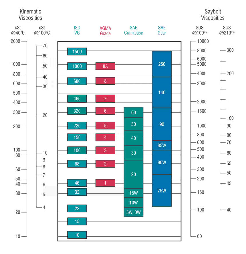
For industrial pump applications that require pumping light oil, please refer to the viscosity classification table and select the oil that is compatible for cSt 32@40 ℃ (ISO 32).
Table: Comparative Viscosity Applications
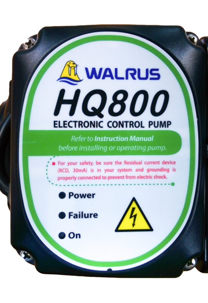
HQ Series Indicator Panel
Walrus America has designed the HQ series pumps for water supply and pressure boosting in residential, commercial and light industrial applications. It is suitable for boosting pressure from underground or surface water supplies. These pumps are designed for use with potable water, clean non-potable water, or other non-corrosive liquids.
The HQ is a complete, all-in-one unit. The system includes a pump, motor, pressure tank, and electronic controller. The built-in electronic controller ensures that the pump starts automatically when water is consumed and operates continuously until water is not required. It will also protect the pump when running conditions are not optimal.
The indicator lights on the top panel of the pump can display the pump’s operating status and help diagnose any issues.
There are 3 indicator lights on the terminal box – Power (Green), Failure (Red) and On (Yellow). The diagnosis of the pump operating condition is as below:
(1) Power (Green): It is lit continuously when connected to power.
(2) On (Yellow): Indicator lights when tap is open indicates normal operation.
(3) Failure (Red): Indicator lights when tap is open the pump has run dry.*
(4) On(Yellow): Indicator lights and flashes intermittently when tap is closed, indicating a pipe leak.
*For more information on dry run automatic shut off, please refer to the instruction manual for the HQ series.
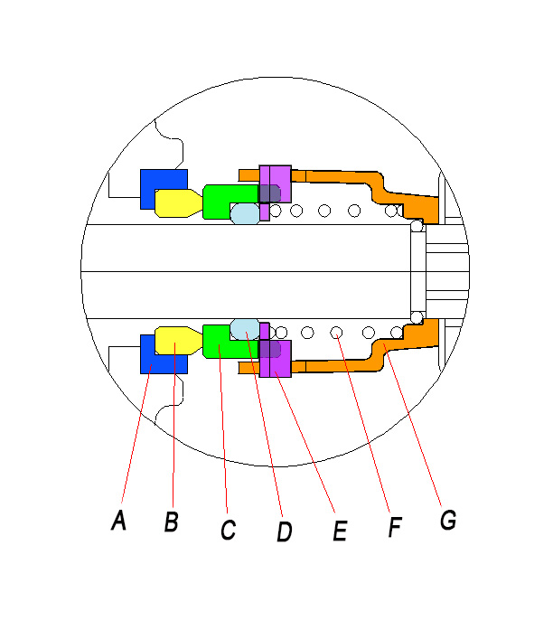
Mechanical Seals
The mechanical seal of a pump is a crucial element to a pump’s function and is often the most common issue when it comes to a pump’s performance over its lifetime. The seal acts as a barrier to prevent liquid from reaching the “dry end” of the pump. Walrus and Systemflo pumps come with spinning shafts while mechanically maintaining fluid contained in the “wet end” of the pump. Figure A shows the cross-section of all the components of a mechanical seal. A mechanical seal consists of a rotary seal (C) next to a driving mechanism which rotates at the same speed as the pump shaft, a stationary seal (B) which mates with the rotary and is retained by a spring (F) that keeps the rotary face firmly positioned against the stationary face. A static sealing gasket (A), O-ring (D), washer (E) and sleeve (G) are strategically located to complete the seal assembly.
Replacing your mechanical seal
If your pump is not functioning as efficiently or leaking near the location at the bottom between the motor and pump casing, it may be time to look into replacing the mechanical seal. The mechanical seal is subject to normal wear and tear over time. The support page on our website has pdf links to procedures on how to replace mechanical seals.
Selecting the right mechanical seal
Many factors need to be considered when choosing the right seal for your pump. Some include pump specifications, temperature, fluid viscosity, and chemical aspects of the fluid. Since it can be complicated to choose the correct mechanical seal for your pump, our technical staff is also available to support you with any questions you may have and consider all aspects of your pump and its applications.